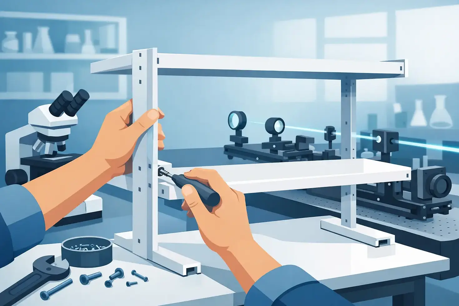
Overtable Shelf Assembly for Optical Labs
- gv9668
- Aug 3
- 6 min read
An optical table can become inefficient long before it runs out of surface area. Power supplies, controllers, computers, fiber equipment, cameras, and measurement electronics often accumulate at the edge of the work envelope, where they obstruct access and complicate cable routing. An overtable shelf assembly creates a defined location for this supporting equipment without claiming the table surface needed for optical layouts, alignment work, and future expansion.
The objective is not simply to add storage above the table. A well-configured assembly must preserve operator access, maintain practical sightlines, accommodate instrument depth and heat load, and avoid creating interference with sensitive experiments. For laboratories working with lasers, imaging systems, metrology equipment, or large optomechanical assemblies, these details affect daily usability as much as the shelf capacity itself.
What an Overtable Shelf Assembly Solves
Overtable shelving is designed to use the vertical space above an optical table for instrumentation that supports, but does not need to sit within, the primary experimental layout. Common examples include laser drivers, temperature controllers, lock-in amplifiers, oscilloscopes, motion-control electronics, monitors, and compact computer systems.
Moving these components off the tabletop has several practical benefits. The table remains available for beam paths and mounted hardware. Instruments are easier to organize by function. Cable runs can be planned from an elevated position rather than draped across an active work surface. It can also reduce the chance that a technician places a heavy or vibrating item directly on a vibration-controlled table during setup.
That said, an overtable shelf is not automatically appropriate for every component. Equipment with substantial weight, high heat output, prominent fans, or a need for frequent front-panel adjustment may require a different location. The shelf should improve the laboratory workflow, not move a problem from the tabletop to overhead.
Start With the Experimental Work Envelope
The first design question is not how many shelves are needed. It is how much unobstructed space the experiment requires.
Consider the full height of mounted optics, posts, periscopes, enclosures, camera arms, and alignment tools. A shelf that appears adequately high above an empty table may interfere once an experiment is built. This is particularly relevant for vertical beam routing, telescopes, imaging paths, and systems that require access from above during alignment.
Depth matters as well. A deep shelf can place electronics conveniently close to the operator, but it can limit sightlines across the table and restrict reaching into the center of a large setup. A shallower shelf preserves more open space while offering less capacity. The appropriate balance depends on whether the table is primarily used for long-term fixed instrumentation or for frequently changing experimental configurations.
Before specifying shelf position, document the largest expected table-mounted assembly and the normal operator work zones. Include required clearance for opening enclosure panels, replacing components, and safely handling laser alignment tools. Designing around the most demanding expected configuration usually prevents costly rework later.
Shelf Height, Reach, and Access
An overtable shelf assembly should support equipment at a usable height rather than merely a convenient mounting height. Operators should be able to read displays, reach controls, connect cables, and remove instruments without climbing, stretching excessively, or reaching across an active beam path.
For routine-use electronics, the lowest shelf is often the most practical location. Higher shelves are better reserved for equipment that needs less frequent adjustment, lightweight accessories, or monitors positioned for viewing. The available ceiling height and overhead utilities may set the upper limit, especially in laboratories with cable trays, ductwork, sprinkler coverage, or suspended laser barriers.
Access from the front and rear of the table is another important consideration. Some labs need open access on both sides for collaborative work, sample loading, or alignment. In those cases, shelf support geometry and shelf depth should be selected carefully so they do not block circulation or create a difficult reach around the structure.
Plan for Service, Not Just Operation
An instrument that fits physically may still be poorly located if its power switch, fuse, cooling intake, or rear connectors cannot be reached. Leave enough clearance for connector bend radius, especially for fiber, coaxial, high-voltage, and motion-control cables. Also consider whether an instrument can be removed for service without disturbing nearby equipment or dismantling the experimental setup.
A practical shelf layout assigns each instrument a clear service path. This can be more valuable than maximizing the number of units placed on a single shelf.
Load Capacity and Structural Considerations
Shelf loading should be evaluated as a system. The total instrument weight, shelf span, support structure, mounting points, and center of gravity all matter. Heavy equipment placed high and toward the front edge can make a shelf less stable and more difficult to use, even when the nominal capacity appears sufficient.
Distribute weight evenly where possible, and place heavier instruments on lower shelves. Equipment should sit fully supported, with no portion projecting in a way that creates a tip hazard or blocks operator movement. If the laboratory requires unusually large power supplies, water-cooling hardware, vacuum components, or battery-backed systems, confirm whether these are appropriate for overtable placement at all.
The relationship to the optical table also deserves attention. An overtable structure can be designed as part of the overall table system, but the intended use must be clear. Sensitive vibration-isolation applications may call for particular attention to structural coupling, equipment mass, and potential sources of mechanical disturbance. Fan-equipped electronics, pumps, and other vibration-generating devices should be assessed individually rather than treated as ordinary shelf loads.
Cable Management Is Part of the Assembly
The shelf becomes most useful when it also creates a disciplined path for cables. Without a plan, overhead instrumentation can produce dangling power cords, crossed signal lines, and difficult troubleshooting at the table edge.
Separate power, data, RF, motion-control, and optical-fiber routing where the application warrants it. Use adequate strain relief so the weight of a cable bundle is not carried by a delicate connector. Route cables with enough slack for normal instrument movement and service, but not so much that loops hang into the experimental area.
Cable routing must also respect laser safety. Do not use a shelf or support structure as an improvised beam block, and do not allow cable bundles to enter a planned beam path. In laser laboratories, the arrangement should remain compatible with beam containment, safety curtains or barriers, warning signs, and the required access to beam dumps and stops.
Configuring Shelves for Different Lab Workflows
The best overtable shelf assembly depends on how the table is used. A photonics development bench may benefit from dedicated positions for laser controllers and diagnostic electronics near their associated instruments. A metrology table may prioritize a clear central work area with a monitor and computer hardware positioned above the rear edge. A university teaching laboratory may need a more adaptable arrangement that can support changing experiments across a semester.
Fixed programs often benefit from a purpose-built layout with defined shelf heights, cable-routing provisions, and instrument locations. Flexible research environments may prefer adjustable shelf positions and open areas that can be reconfigured as experiments change. Neither approach is universally better. The deciding factor is the expected rate of change and the consequences of downtime when an experiment must be rearranged.
Material selection can also depend on the environment. Cleanroom-adjacent spaces, corrosive-process areas, and laboratories with strict cleaning procedures may have requirements beyond standard equipment storage. The shelf design should be evaluated alongside the optical table material, support configuration, enclosure needs, and laboratory operating practices.
Information to Define Before Ordering
A productive technical discussion begins with the table dimensions and support arrangement, then moves to the equipment the shelves will carry. Provide the approximate size, weight, and quantity of instruments, along with preferred shelf locations and any height restrictions. Identify components that produce heat, vibration, or unusually large cable bundles.
It is also useful to describe the experiment itself. A shelf assembly for a compact laser characterization setup will be configured differently from one intended for a large imaging platform or a semiconductor inspection station. Photos or layout drawings can help identify conflicts that are difficult to capture in a short parts list.
VERE can work from these real-world constraints to configure overtable equipment around the table, instrumentation, and operating workflow. The most effective arrangement leaves the experiment accessible on day one and still gives the laboratory room to change six months later.


Comments